Using Cellular HAT GNSS with no USB

Hello, I have
Cellular IoT HAT – LTE-M
modem PPP communication over UART ttyS0
for GNSS reading I have to use USB port and cord, which is ugly solution,
because I have to drill a hole in case to plug-in USB cord.

Is there a way to use GNSS functionality other nice way?

Hi @dima

Board: https://sixfab.com/product/raspberry-pi-lte-m-nb-iot-egprs-cellular-hat/
Raspberry Pi version: ?
OS: ?
Any other relevant specifications:

Problem: You are using PPP to over /dev/ttyS0 to access the data-network - (is this working?) You would like to be able to access the GNSS data simultaneously with the PPP, but without using USB (as there is not a practical/feasible way to route a USB cable in your case) - is this correct?

Solutions Tried:

Solutions Considered (but are unsure of):

Alternate Solutions that are possible (but maybe not preferred)?


In anycase, if I have understood the problem correctly, a great place to start would be to have a read of the Hardware Design Guide for the BG96 (https://www.quectel.com/UploadImage/Downlad/Quectel_BG95_Hardware_Design_V1.1.pdf) - on page 14 is a description of the available UARTs - there are three

  • Main (for data and AT)
  • GNSS
  • Debug

for your use case, you are currently using the Main, as that is where the PPP/AT commands are being sent (and I am assuming are working).

if you look at page 18 in the hardware guide (the pinout for the BG96) you will see the main UART is on pins 30, 34:39 and GNSS is pins 27/28, Debug is pins 22/23 - so the GNSS is a physically different UART on the BG96.

if we look at the schematic for the HAT (https://github.com/sixfab/Sixfab_RPi_CellularIoT_HAT/blob/master/schematics/RPi_Cell_I1oT_Hat_v1.3.0.pdf) - we can see the GNSS pins are routed to a level translator and then to Pins 12 & 13. The Main UART is routed to the Pi’s standard UART;

So, this explains why it’s not working for you - the UART you are accessing, ttyS0, is routed to the modems main UART.

The Pi’s UART setup is here: https://www.raspberrypi.org/documentation/configuration/uart.md - it’s not well documented, but I believe on the Pi 4, there are additional UARTs on GPIOs 12/13. So, if you have the Pi 4 you can set the additional UART up and access GNSS over that UART (it’s not enabled by default). On the Pi 3 you would have to somehow get a UART on GPIO12/13, for example writing a software-UART that reads the GPIOs - now this is likely to be terrible and slow, due to the Pi not being tight on timing, but for GNSS might work ok - try and report back!

some links to look at
(Pi 4 UARTs)
https://www.raspberrypi.org/forums/viewtopic.php?t=244827

(Software UART over GPIO)
https://www.raspberrypi.org/forums/viewtopic.php?t=35544

Now, on the USB, the BG96 works a bit differently, the USB Option driver presents 4 virtual serial ports - ttyUSB0-3 - 0 = debug, 1 = GNSS, 2 = AT, 3 = PPP and hence you can have GNSS; AT and PPP all at the same time.

you see. Using main UART - PPP only

If we use USB cord, we can get use of PPP, GNSS, and I believe AT for (AT+QGPSLOC=2?)
but USB cord does not suite to any of RaspberryPi cases(boxes) to hide it inside of the installation. I have to drill a hole corpus and have USB cord wired outside, which is anyway ugly solution for a device to be used in field.

Can SixFab deliver a custom PCB design? e.g perhaps all we need is to solder microUSB port differently, so we can hide USB cord inside of case?
Image 2020-10-09 at 10.02.47 AM

I won’t speak on behalf of SixFab, but a custom board like that would likely be a lot of work, and cost for a rather niche use-case. Not that I don’t agree with you - I have had similar issue where the ports on boards are just in the wrong place and it make a case a nightmare - i used it as an excuse to buy a 3D printer and make my own cases (be careful it can be addictive)

I had neglected another option - if you are ok with using the main UART (which you apparently are!) you might be able to use CMUX - which creates virtual serial ports over the main physical UART. You need the driver on the Pi side, and also the modem needs to support it. I have had issues in the past with CMUX (you can find my post here: PPP, CMUX, ldattach on Raspberry Pi with M95) so you’re mileage may vary. I’m fortunate enough to have a Quectel LTE EVB with a BG95 and it appears to work fine on that, so in theory it should work.

Hi @sixfab-0272
much appreciated the advice on CMUX, but I see even if solution is working sharing main UART for different tasks still can be stability issues for the modem.
As pins 32-33 on the HAT header are used for GNSS, can we use serial expansion HAT
https://www.waveshare.com/serial-expansion-hat.htm to communicate with GNSS features ?
Also, there is there on the HAT QWIICK - I2C connector. Can we communicate with modem over I2C?

Howdy

Apologies in advance - answering on mobile whilst on the run and will look closer when I’m back at my desk (especially with regards to pin contention; I’m pretty sure that’s not an issue (unless you go out of your way to make it an issue!) but I’d want to confirm when I can look at the datasheets again)

I don’t think the waveshare board will work as it takes an I2C interface and converts it into dual uart. These UARTS are then made available to another set of pins (separate to the main pi GPIO header) - so you would need to route those new uart pins back to the SixFab shield’s gnss pins… somehow - at at that point your routing another cable and have another board to deal with.

Honestly - I would

  1. Upgrade to a Pi4 and use alternate pin functions
  2. Use CMUX to multiplex the main UARTs
  3. Use a software hack to run UART over GPIO
  4. Find a bigger case - if size is not a major issue, there are some large metal IP67 cases (that I know of) that are designed to house 3 extra HATs. There are other options depending on other needs
  5. Design a custom case

These will be the smoothest options in the long run

back at the desk - so you can see the issue im referring to with the waveshare expansion hat in this image
image

now as per pin contention - if you look at the docs here: https://docs.sixfab.com/docs/raspberry-pi-cellular-iot-hat-technical-details#section-pinout, assuming you have v 1.3.0 (sorry, didn’t ask which version you had) - there are two solder points you can connect to activate the GNSS UART. They are connected by default apparently, so be default the GNSS UART is connected. If you are concerned for Pin contention you can cut those connectors and you are fine - then obviously if you want to revert you need to resolder them. You can also see the solder points on the schematics as well.

as for the QWIIC connector, that won’t help you - its only breaking out the I2C side of the GPIO header - it’s not going anywhere near the modem.

thank you for supporting @sixfab-0272
so GNSS UART pins 32-33 on the header.
I still cold not figure out clear article/documentation on using UART over GPIO
Can you say the GNSS UART accepting AT commands? or just posting nmea sentences all the time?
RPI4 isn’t option, cos of cost and power consumption.

is CMUX possible on GNSS UART pins 32-33 ?

as you are probably well aware the UART here is an asynchronous serial communication line. Asynchronous being the key word - this means there is no clock signal in place, hence there are only two pins in use (one for receive and one for transmit). Since there is no clock in place, the timing of the pulse-train needs to be tightly controlled. The receiver is going to sample the square wave regularly and note whether it’s high or low. This sampling needs to always be inside the pulse - so you have a margin of error of +/- 0.5 pulse width (assuming you’re aiming to sample in the middle of the pulse).

for dedicated HW this is easy for systems like the Pi though it’s harder. The reason for this is that OS’s like Raspbian are not able to guarantee the timing of operations. So, when you try and do things that require tight timing (like sampling a serial line), the timing can be so bad that you just completely misread the data.

so if you are going down this path, then you need to write some code that will sample the GPIO pins consistently enough to reconstruct the data line, and you will find that the upper limit of baud rate is pretty low for reliability. A few posts up I posted a few links, I’ve never tried it myself though so can’t provide any feedback. if i get some spare time I might try it as it’s an interesting challenge

From my experience (using the serial option driver) you enable GNSS via an AT command on the main UART. You then just get NMEA data streaming constantly on the GNSS UART - you can’t post AT commands or run PPP on that UART

it wont be possible to CMUX the UART on pins 32/33 as its a dedicated GNSS UART, its only the main UART that is able to be CMUX’d - as i type now, I’m not sure if you can get NMEA data on a CMUXd UART though - a typical use case for CMUX would be to have a PPP and AT command simultaneously. sorry for that oversight.

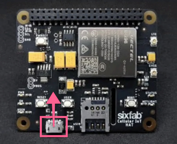
I’m just looking at the GNSS Application Note, AT+QGPSCFG sets the output port for GNSS, you can choose none, usb, uart or aux (aux refers to the debug UART) the debug port though doesn’t appear to be connected on the HAT you have.

how often do you need to get location information? there is AT+QGPSLOC which will give you the location data in response. Since you have a PPP session you would either need to disconnect that session to send the AT command. Otherwise use CMUX to the main UART then keep one for PPP and one for AT - again, not tested

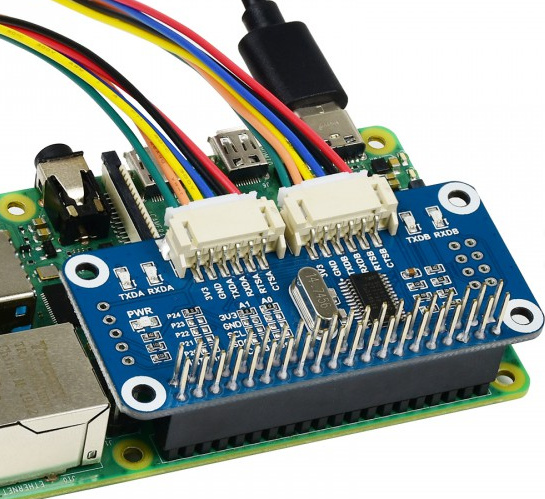
looking back at the waveshare - there is a single pin contention between the Pi and the expansion hat - Pin24 which is used for IRQ on the waveshare is also the Powerkey on the IoT HAT. So, you would need to sacrifice that to use the waveshare…and then deal with that the GNSS UART pins go to the Pi and the Waveshare - so you would route a cable from the RX/TX on the waveshare back to pins 32/33 on the HAT… so you would need to absolutely guarantee nothing stray will come from the Pi itself on those pins… not sure how good a solution that would be… so that whole solution is getting kinda crazy… and messy. The concept of the Waveshare is cool - you could make your own with a proto board and header - then just connect the pins you want to - but more work than it’s worth perhaps

a couple more options anyway - this conversation is good for me, its forcing me to think outside the box and a few thigns im interested to try myself. But ill be fascinated to see what the end result it!

lets summarize. Waveshare serial expansion board allows to RPI to have visible 2 UART ports. e.g. /dev/ttyUART1, /dev/ttyUART2 - when this HAT is on the RPI.

then I have to settle Cellular HAT above of WaveShare, but pins 32-33 of the Cellular HAT must be wired to somewhere on the WaveShare HAT header, not into pins 32-33 of the WaveShare.

but perhaps WaveShare board has configuration software, that can deploy pins 32-33 as UART, plus I have to disable pins 32-33 on RPI with GPIO library, to make them invisible to RPI.

hi @dima - sorry have been away for a while! 21 days apparently! but looking back at the posts now, not sure I can be of much more help

hope you find you a good solution - please post back if you do!

Hello Sixfab-0272, good to hear from you again!
even using USB cord for GNSS is a problem.
RPI assidentally re-enumerates USB ports in run-time, so for example ttyUSB2 dissapears and ttyUSB4 appears but that happens randomly. So my GNSS daemon crashes.
I tried to use symbol links by creating rules file in /etc/udev/rules.d/ following to tutorial https://www.freva.com/2019/06/20/assign-fixed-usb-port-names-to-your-raspberry-pi/
e.g SUBSYSTEM =="tty", ATTRS{idProduct}=="0296", ATTRS{idVendor}=="2c7c", SYMLINK+="ttyUSB_DEVICE2" but that makes no sense, since USB port number accidentally changing to the symbolic link either. So my question: Is there a way to enable only particular USB port, eg. ttyUSB2 to be a static port on RPI?

found the reason why ttyUSB2 disappears.
It happens because IOT Hat does re-set(turnON/OFF) when cellular connection lost.
so nothing I can do with GPS reading over USB, than try->ttyUSB2->except->try->ttyUSB3 and so on till working port is found.

1 Like

@dima great work, thanks for posting back; sorry i wasn’t able to help further - hopefully this information will help someone in the future