Is it possible to use the SPI0 or SPI1 interface while the hat is on? I have an SPI-based e-paper display for my project that I want to use.
From the required SPI pins, I see the SPI0 CLK pin used for Power Key, SPI0 MOSI for OPTO#1, SPI1 MOSI used for BG96 Status. I tried hooking up a device to SPI0-CE0, but it did not work and must have conflicted with the hat.
If I can reroute the BG96 Status signal to another pin (or disable it), that would be perfect.
I am planning now to use the SPI1 interface and not have the hat directly sitting on the RPi and only wire over the needed pins for the hat to work. Though having the hat on would be must easier.
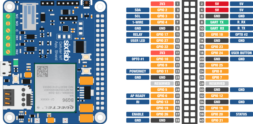
If we compare the SPI pins(SPI0 pins are GPIO 7, 8, 9, 10, 11
SPI1 pins are GPIO 16, 17, 18, 19, 20, 21) and the pinout of the Cellular IoT Application shield, we can see that there are conflicts in the pins.
Unfortunately, the Shield doesn’t have any solder jumper to disable any of these pins.
Thanks for confirming. I an now interfacing with the shield using jumper cables and rerouted the two conflicting GPIO as mentioned avoid. It appears to work well so far.