I am trying to use the UART port on the Raspberry with the shield.
The UART port is already set up properly but I am still not getting data from the 4G module.
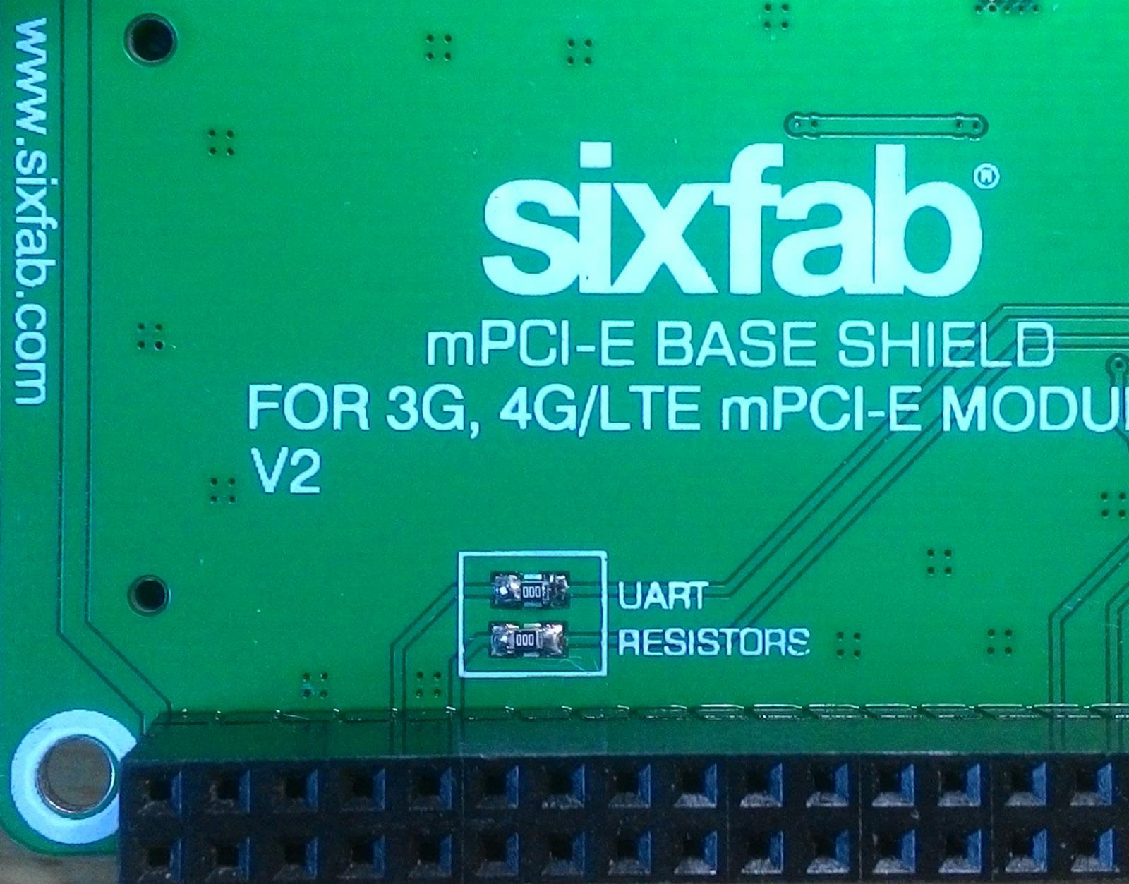
I Have seen in other topics that I need to bridge the UART resistor sections available under the shield.
Could anybody tell me which resistor do I have to put there? Which type and value?
cheers - i dont have my board handy just now - what size pads are they - is it 0805? thinking to put some jumpers on instead so i can selectively enable or disable the UART
in the case I refer to here, I am using the LTE Base Shield (https://docs.sixfab.com/docs/raspberry-pi-3g-4g-lte-base-shield-introduction) - on the reverse of the board are two sets of solder pads - one on the UART RX line and the other on the UART TX line; by default (as shipped from the factory) these are open-circuit, thus the Modem sockets UART lines are disconnected from the shields header pins. The implication being that, if you stacked another shield/HAT that required the UART, then that would be fine. In this scenario you must use the USB connection from the Pi to the shield.
If you solder a 0 ohm resistor - or jumper over those pads, then the Pi’s UART RX/TX are now connected to the shields modem socket - you are free to use either UART or the USB. However, the Pi’s UART (pins 14/15) is now taken by the shield, and can’t be used elsewhere (otherwise you will have conflicts)
in my case - i have the LTE Shield and an RS-232 shield - so I have to choose what I want to use. I have specific cases where I want the modem over UART and others when it doesn’t matter, but I need the UART elsewhere, so i would like to put some jumpers on those pads instead of 0 ohm resistors.
but as this thread refers to the LTE Base Shield V2 - it might be worth posting your question to another thread to get the right attention as you refer to a different board
cheers - is there an 0805 jumper? quick google says “not really”… but im probably wrong… if not, there is the possibility to remote mount something and a bunch of other solutions - so a 0 ohm might actually work (and then i just need to buy another board when it doesnt, right?!)
out of curiosity, is there a reason for not making them a more flexible option? like even a 1210 footprint or through-hole? i see there is an updated version now https://docs.sixfab.com/docs/raspberry-pi-3g-4g-lte-base-hat-faq and these are even smaller solder-pads by the looks of it.
If you are communicating over USB and want to use UART instead, just follow these instructions to change PPP to use UART -
Keep in mind that you will not be able to use GPS/GNSS because it will only work over USB. But is you do not need those then this will eliminate the need to use the USB cord.